What is free cooling?
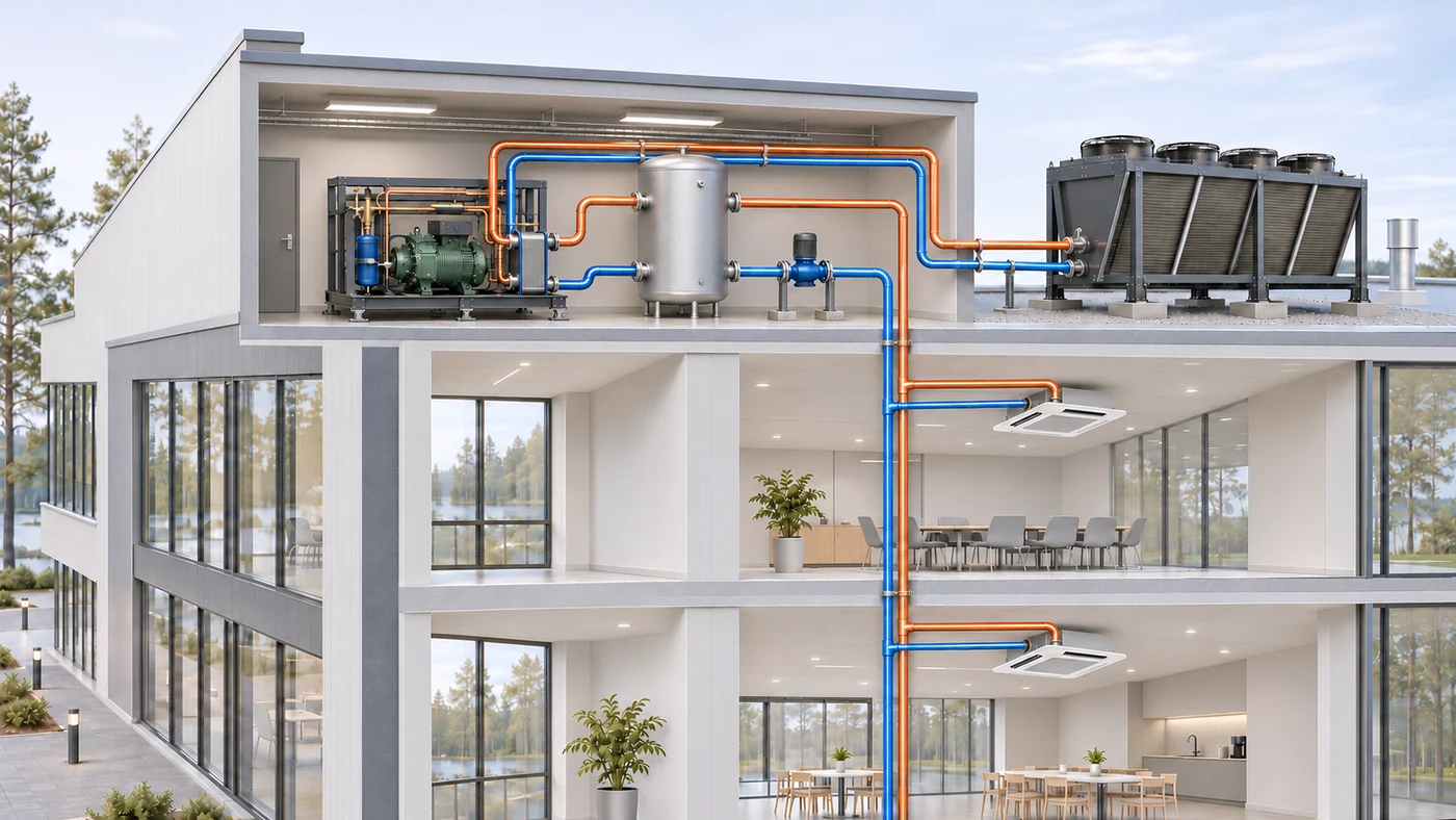
Free cooling uses cool outdoor air to remove heat from a building. In this system, ceiling cassettes transfer heat from the rooms to a circulating water-glycol solution. The warmed fluid releases heat to the outdoor air at the rooftop dry cooler. The outdoor and indoor air streams remain separate.
The available cooling depends on outdoor temperature, the fluid supply setpoint, the cooling load and the capacity of the coil and fans. The coil needs a temperature difference between the fluid and outdoor air. As outdoor air gets cooler relative to the supply setpoint, free cooling can cover more of the load.
Open simulator (Finnish)How does it differ from mechanical cooling?
In mechanical cooling, the fluid transfers heat to a refrigerant in the evaporator. The compressor raises the refrigerant vapour pressure and temperature so the condenser can reject heat. The simulator shows how a heat recovery circuit can use that condenser heat.
In partial free cooling, the dry cooler cools the fluid and the compressor covers the remaining load. When free cooling covers the full load, the compressor can stop. The three-way valve splits the fluid flow between the dry cooler coil and the bypass.
Where do the cost savings come from?
Free cooling reduces compressor electricity demand and operating hours. Fluid pumps and dry cooler fans still consume electricity. Net savings arise when the avoided compressor energy exceeds the additional electricity used for free cooling. Fewer compressor operating hours may also reduce wear.
Annual savings depend on cool operating hours, the cooling load, fluid temperatures and electricity prices. When the system recovers condenser heat for heating, reduced compressor operation also reduces the available heat. Include the cost of replacement heat when comparing total operating costs.
Getting started
- Set the cooling load and temperatures. Enter the load of each ceiling cassette in kilowatts. Set the outdoor temperature, fluid supply setpoint and return temperature. Start by varying outdoor temperature while keeping the other settings fixed.
- Start the pumps and enable automatic control. The controller adjusts free cooling and starts the compressor when the dry cooler cannot cover the full load. Watch the flow split at the three-way valve, the fans and the running status of the pumps and compressor.
- Try manual control. Turn automatic control off and adjust the flow to the dry cooler. At 0% the fluid takes the bypass, and at 100% it passes through the coil. Try intermediate positions. Request compressor operation when needed. The simulator checks the remaining cooling demand in manual mode as well.
What can you observe in the diagram?
Pipe colours and moving dots show the fluid and refrigerant circuits. Open and close cutaway views of the equipment and pipes. Watch the colours progress through the refrigerant circuit at compressor startup. The heat recovery pump starts three seconds before the compressor and stops three seconds after it.
Change fluid type, freeze protection, specific heat capacity and circuit pressure. On the refrigerant side, select a refrigerant and adjust evaporating and condensing pressures to see how they affect compressor power and COP.
What does the State points view show?
- Cooling and heat recovery. See free cooling output, the cooling duty remaining for the compressor and any unmet load. Heat recovery output and daily energy are based on calculated condenser heat.
- Flow and pumping. Inspect mass and volume flow, viscosity and specific enthalpy. Change circuit pressure drops and compare pumping power and cost for glycol solution and water.
- Electricity use and cost. Set the electricity price and operating hours. Open Tilapisteet (State points) to see daily electricity use and cost for the compressor, pumps and dry cooler fans in the current operating state.
Compare three operating modes
Keep the cooling load, fluid supply setpoint, electricity price and operating hours fixed. Start with warm outdoor air and lower its temperature in steps. Record electricity use and cost for mechanical cooling, partial free cooling and full free cooling. Check whether the system meets the full cooling load at each step and compare the heat available for recovery.